|
|||||||||||||||||||||
|
|||||||||||||||||||||
SCIENTIFIC BLOGReactive solutions, a solution for CO2 leakageIn the unlikely case of localized CO2 leakage from the storage reservoir, it is desirable to close the leak quickly, efficiently and permanently. This could be done by blocking the leak path (such as a permeable fault or along a wellbore) by material precipitation. With regard to permanent closure, it is logical to look into materials that occur naturally in the subsurface to block the leak. Natural minerals are stable on the long-term which ensures permanent CO2 containment in the storage site. Here we will describe our work to investigate if injection of reactive solutions to block CO2 leakage is a feasible method of leakage remediation. Injecting reactive solutions to form solid reactants
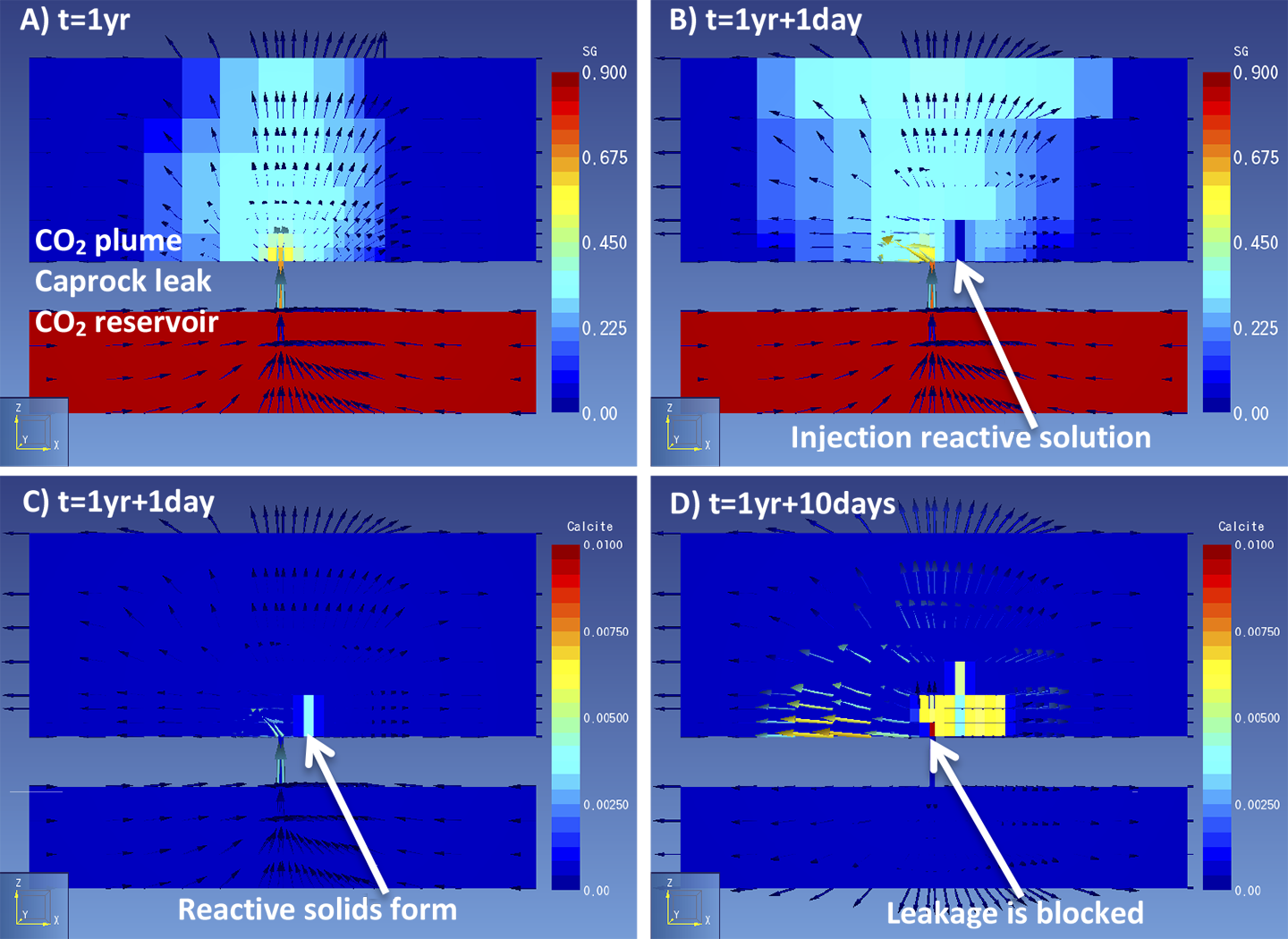
We performed reactive transport simulations of reactive solution injection into a plume of leaked CO2 with the software TOUGHREACT. A 200 by 200 m model was created of a CO2 reservoir at the bottom, an aquifer at the top and on a cell connecting the two layers, representing a caprock leakage pathway. Several reactive fluids could be used, we chose a calcium based solution which forms calcite when injected into an CO2-containing environment. First, CO2 is allowed to leak for several years to let a CO2 plume develop in the top aquifer (Figure 1a). This takes into account the time required for a plume to become large enough to be detected by monitoring techniques. Second, a reactive solution is injected into the CO2 plume (Figure 1b), to stimulate the formation of CO2-reactive solids (Figure 1c). Injection continues until flow is no longer possible as the solids fill the pore space in the rock and block the flow (Figure 1d).
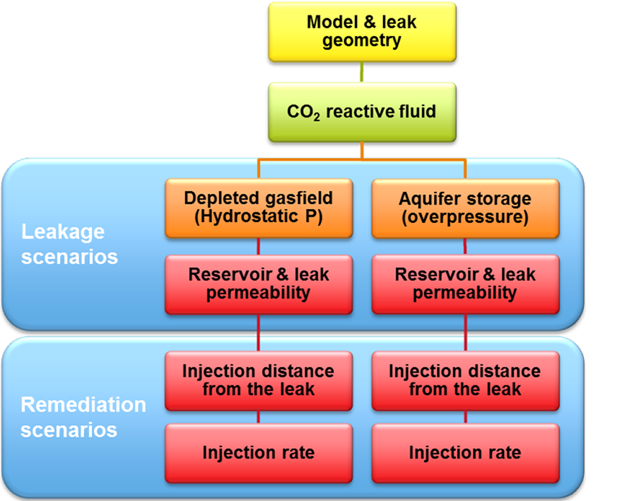
Figure 1. Simulation results of a) gas saturation shows a CO2 plume over a caprock leak; b) gas saturation shows the first injection of a reactive solution; c) calcite content shows precipitation of a solid reactant; d) calcite blocks the leak and of gas movement through the leak stops. One can imagine that several factors control whether solid reactants form in the right amount at the right location to stop flow. When solids form too fast they may not reach the leak, or when the CO2 leaks too fast the solution may not be able to suppress the gas leak. To study how effective solid reactants are to block CO2 movement, several model scenarios were run. The scenarios represent a range in possible characteristics of the leak and the injection that could affect the success of leakage remediation (Figure 2).
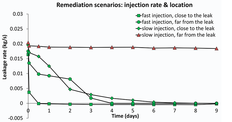
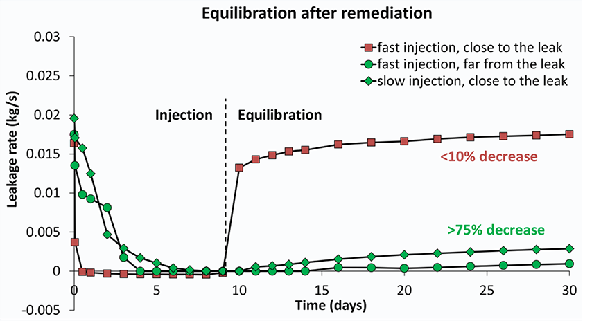
Several models were built with different rock properties (porosity and permeability) which control how easy gas and fluid can flow through the rock. For each set of rock properties, scenarios were run of injection at different distances to the leak point and injection rates. The results for the efficiency of leak closure by calcite precipitation vary significantly; from hardly any effect to complete leakage remediation (Figure 3). Was clogging and leakage remediation successful?It is important to check with the model if the remediation effort remains successful after injection is stopped. This is especially relevant since CO2 flow cessation is only partially due to pore blockage by calcite. In addition, the gas leakage is suppressed by the water flow. The injection simulations were first run until the CO2 flow ceases. In a next run, the injection was stopped manually at that point and the model was allowed to equilibrate so we can see if gas starts to flow again. The three scenarios that were able to stop leakage during remediation (Figure 3) are now shown to have succeeded only partially (Figure 4). The degree of leakage reduction can be used to calculate the likelihood of success and to provide input for the Mirecol webtool. This tool will help site owners to find appropriate remediation methods in the unlikely case that CO2 leakage occurs.
Laura Wasch |
| ||||||||||||||||||||
| Ensuring safe, reliable, and controllable CO2 storage | |||||||||||||||||||||
 |
|||||||||||||||||||||

 THE PROJECT
 SCIENTIFIC BLOG
 EVENTS &
 PUBLICATIONS
 PARTNERS